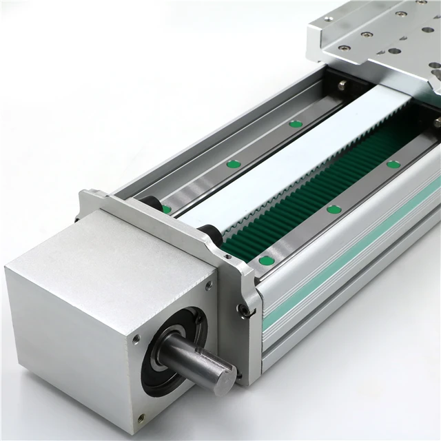
Long-stroke GY-EGHP95F-II modules—especially those running 1000 mm up to 2500 mm—will not tolerate a warped bed. The extruded aluminum shell packs internal rails and drive screws into a tight space, so if you bolt it onto a rough steel tube frame, the whole module twists with it.
If your frame rail dips more than 0.03 mm over a meter, cranking down anchor bolts will twist the actuator body right out of square. That twist pinches the internal carriage sliders, spiking motor current and causing noticeable speed ripple during multi-axis interpolation.
Before setting the module in place, lay a precision straightedge down the steel frame. Drop ground steel shims under any low spots so the module sits flat with zero built-in stress.
Set the GY-EGHP95F-II module onto your shimmed frame and thread the bed bolts hand-tight. Set a dial test indicator on a reference bridge, touch the tip to the slider top, and roll the carriage from end to end. Tap the module until your straightness and parallelism stay locked under 0.015 mm per meter before torquing frame bolts from the middle out to the ends.
Next, mount the servo or stepper motor using the flexible coupling and adapter flange. Never force the motor shaft into the coupling bore—if the shaft drags, check for burs on the keyway or keyless clamp ring. Torque the flange bolts to spec and tighten the coupling pinch screw through the access port.
For lubrication, access the internal guide sliders and drive screw through the side grease ports. Inject NLGI Grade 2 lithium grease every 200 operating hours or 500 km of travel. Wipe down the top stainless strip seal to clear away metal grit before it gets dragged into the housing cavity.
A: The frame mounting surface dips or twists at the ends, pulling the module body out of square when the anchor bolts were torqued down. Loosen the end mounting bolts, shim the frame gap until flat, and re-torque while watching a dial indicator.
A: Vibration can shift the optical or inductive proximity sensor inside its aluminum side slot. Wipe coolant mist off the sensor face, verify the target flag clearance sits at 1.0 mm to 1.5 mm, and apply medium-threadlocker to the sensor bracket screws.
Shim frame surfaces flat, check slider alignment with a dial indicator, and keep the strip seal clean—that covers 90% of field integration steps for GY-EGHP95F-II actuators.